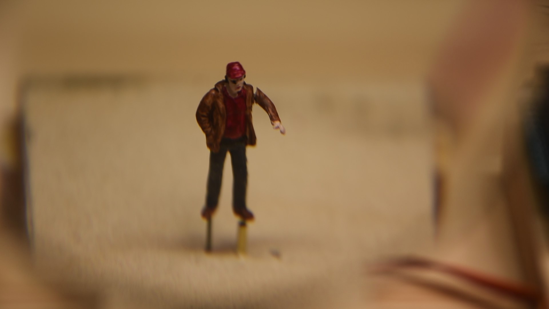
I’d been looking at some other modeler’s efforts at animating figures and objects lately, especially work by Laurie McLean from Australia. He does some really amazing animations using small gear motors, Wow! This got me thinking I’d like to try my hand at it. I recently got some unpainted HO scale figures so I selected a likely candidate to experiment with.
I used a drill bit in a pin vice to machine a slot in this fellow’s back to make room for the linkage. I amputated an arm, then drilled a hole up through his leg, hoping to hide as much of the mechanism as I could. I could not get one hole up through his leg and back in one shot with my .016″ drill, so I had to remove a bit of the back of his leg and start a new hole up into his lower back at a slightly different angle. I then cross drilled through his shoulder for the axle that would hold his arm. I drilled this for the 3/64″ brass bushing shown here on the 1/32″ music wire axle. This bushing was super glued into the far recess in his back to support the axle on one side. I slid it down the axle and used a length of the 3/64 tubing to press it into place while gluing. I cut another bushing about .09″ long to be installed in his shoulder later to support the other end of the axle.

I drilled a 1/32″ hole and a .015″ hole in a strip of .016″ thick brass, then cut and filed it to make the lever. I soldered this to a piece of 1/32″ piano wire with about .060″ protruding on one end to go into the installed bushing and an inch or so on the other to use as a handle.

I inserted the long end of the axle through the slot and hole in the shoulder and worked the short end of the axle into the bushing already in place. Next the second bushing was slipped onto the axle and glued into the hole in the shoulder. After the glue dried, I cut off the axle so it just protruded from the shoulder. I drilled a shallow hole in the arm and glued it onto the axle. I ran a .01″ phosphor bronze wire up through the leg and bent an angle and inserted it into the lever. This was tedious and I ended up drilling the hole out to .02″ in the lever and clearing out some of the slot. You can see the assembly below.

In order to test this out I made a plywood stand and attached a servo below to drive the figure. Upon testing, I realized the .01″ wire was too flimsy to drive the mechanism unsupported so I added a brass tube to guide it. I hooked the servo up to my trusty Arduino with three connections, +5V to red, Ground to Brown, and digital pin 3 to orange, wrote a quick sketch and viola! Link to video here. Now I need to paint the figure and come up with some activity that he could be preforming, throwing a horseshoe?
Lessons learned:
- The brass bushing idea works well.
- The .01″ actuating wire is too flimsy, I might try .015 or .020″ next time.
- The connection to the lever is difficult, with thicker wire might be impossible. I need to come up with something for this.
- I need to consider how the figure is to be placed on the layout, I need a way to easily install it with the servo and linkage intact.


