
I got my first (of many) semaphore working last week. For my initial test, I used one of my turnout decoders to operate it. I’ll need those for turnouts (plus a few!) so I designed a new decoder for the signals. It is a simplified version, based on my turnout decoder. Of course the code for the Arduino was modified heavily since the JMRI signal head I’m using outputs a different loconet switch address for each aspect displayed, three in total, green – yellow – red.

I got out my trusty old Corel Draw and created a photomask which I printed on transparency film on my inkjet printer. I actually made four copies so I could make four boards at a time. I then cut some pre-sensitized circuit board, placed the film upside down on it and exposed it to UV light, the standard fluorescent bulb on my magnifying viewer seems to work OK. After 8-10 minutes I placed the board in positive developer solution and washed off the un-exposed coating.

I then placed the board in ferric chloride solution which dissolves the uncovered copper. This takes a while, 10 minutes or so if you raise the temperature of the solution. I have a cheap little crock pot for this purpose. Do not get this stuff too hot! Rinse the board in water, drill holes in the small bare spots left from the mask as a guide. I use a .030″ carbide drill and then open up a few of the holes as needed.

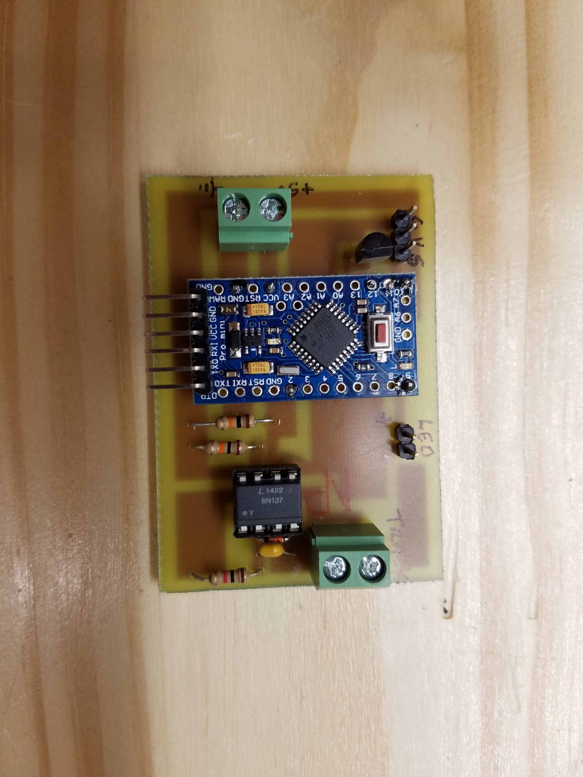
Now I’m ready to add the components.

I can load the program for the signal and it actually works! There are connections for 5V in – top, the servo – top right, the signal LED middle right, and the track DCC signal bottom. With the Arduino Pro Mini, optocoupler, transistor, 3 resisters, a diode, a capacitor, and the board fabrication, I figure each of these cost around 6-7 dollars. Of course my time is free!